Iranian Classification Society Rules

< Previous | Contents | Next >
APPENDIX 3-1 Regulation on Technical Conditions
1. General
The provisions of this Regulation set the technical requirements that containers, which they transport under Customs seal, are to meet for being approved by the Society.
2. Basic Principles
Approval for the international transport of goods under Customs seal may be granted only to contain- ers constructed and equipped in such a manner that:
(1) No goods can be removed from, or introduced into, the sealed part of the container without leav-
ing visible traces or without breaking the Customs seal;
(2) Customs seals can be simply and effectively affixed to them;
(3) They contain no concealed spaces where goods may be hidden;
(4) All spaces capable of holding goods are readily accessible for Customs inspection.
3. Structure of Containers
(1) The constituent parts of the container, door and all other closing systems, apertures for ventilation and drainage are to comply with the requirements in 2 above.
(A) Constituent parts of the container
(a) The constituent parts of the container such as sides, floor, doors, roof, uprights, frames, cross-pieces, etc. are to meet the following requirements.
(i) These are to be assembled either by means of devices which cannot be removed and re-
placed from the outside without leaving visible traces or by such methods as will pro- duce a structure which cannot be modified without leaving visible traces.
(ii) When the sides, floor, doors and roof are made up of various components, these are to meet the same requirements and be of sufficient strength.
(b)
Joining devices for assembly of constituent parts are to be constructed by the following methods.
(i) Where joining devices (rivets, screws, bolts and nuts, etc.) are used, a sufficient number of such devices are to be inserted from outside, traverse the assembled constituent parts, protrude inside and there be firmly secured. However, conventional rivets (rivets whose
placing requires handling from both sides of the assembly of constituent parts) may also be inserted from the inside.
(ii) The following methods are to be used, in principle, for securing firmly.
① Welding
② Riveting (except expansion rivets, blind rivets and the like)
③ Bushing the protruded end
④ After bolting, swaging the protruded end of bolt
⑤ After bolting, welding on the nut
(c) Notwithstanding the above, load compartment floors may be secured by means of self-tap- ping screws, or self-drilling rivets or rivets inserted by means of an explosive charge, when placed from inside and passing at right-angles through the floor and the metallic cross-pieces underneath, on condition, except in the case of self-tapping screws, that some of their ends be flush with the level of the outside part of the cross-piece or be welded on to it.
(d)
The number of joining devices is to be so sufficient as to give the assembly of constituent parts enough strength.
(e) Where, due to technical reasons, it is not practicable to secure parts in the manner described in sub-paragraphs (b) and (c), the constituent parts may be joined by means of the devices such as expansion rivets, blind rivets, and the like of this note provided that the devices used on the inner face of the wall are not accessible from the outside.
(B) Doors and other closing system
(a) Doors and all other closing system (including stopcocks, manhole-covers, flanges, etc.) are to comply with the following requirements.
(i) These are to be fitted with a device on which Customs seals can be fixed. This devices must be such that it cannot be removed and replaced from the outside without leaving
visible traces.
(ii) The doors or fastening must be unable to be opened without breaking the Customs seals. Also the Customs seals are to be adequately protected.
Ap p e ndi x 3- 1
![]()
(iii) Containers comprising a large number of closures must be designed so as to keep the number of Customs seals to a minimum. To this end, neighbouring closures must be in- terconnected by a common device requiring only one Customs seal, or must be provided with a cover meeting the same purpose.
(b) Containers with opening roofs must be constructed in such a manner as to permit sealing with a minimum number of Customs seals,
(c) The device on which Customs seals can be fixed must:
(i) be secured by welding, or by not less than two joining devices complying with the re- quirements in (b) and (c), (a), 3.
(ii) be so designed that when the load compartment has been closed and sealed the device cannot be removed without leaving visible traces.
(iii) incorporate holes of not less than 11 mm in diameter or slots of at least 11 mm in
length by 3 mm in width.
(iv) afford equal security whatever type of sea is used.
(d) Butt hinge, strap hinges, hinge-pins and other devices for hanging doors and the like are to comply with the following requirements.
(i) These must be secured in conformity with the requirements in (i) and (ii), (c).
(ii) Moreover, the various components of such devices (e.g. hinge-plates, pins or swivels)
must be so fitted that they cannot be removed or dismantled when the
load compart-
ment is closed and sealed without leaving visible traces. However, where such a device
is not accessible from outside it will suffice it, when the door or the
like has been
closed and sealed, it cannot be detached from the hinge or similar device without leav- ing visible traces.
(iii) Where a door or closure-device has more than two hinges, only those two hinges near-
est to the extremities of the door need to be fixed in conformity with the requirements in (i) and (ii), (c).
(e) In the case of thermal containers, the Customs sealing device, the hinges, and any fittings, the removal of which would give access to the interior of the load compartment or to
spaces in which goods could be concealed, may be fixed to the doors of such load com-
partments by means of set bolts or set screws which are inserted from the outside, on con- dition that:
(i) the tails of the set bolts or set screws are fixed into a tapping plate or similar device fitted behind the outer layer or layers of the door structure.
(ii) the heads of the appropriate number of set bolts or set screws are so welded to the
Customs sealing device, hinges, etc., that they are completely deformed and that the set bolts or set screws cannot be removed without leaving visible signs of tampering. (see
Fig 1).
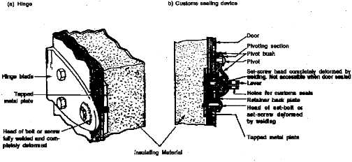
Fig 1 Example of Hinge and Customs Sealing Device on Doors of Thermal Containers
(C) Ventilation apertures and drainage apertures
(a) Apertures for ventilation and drainage are to be provided with a device preventing access to the interior of the container. This device must be such that it cannot be removed and re- placed from outside the container without leaving visible traces.
Ap p e ndi x 3- 1
![]()
(b) Ventilation apertures are to comply with the following requirements.
(i) Their greatest dimension must, in principle, not exceed 400 mm.
(ii) Apertures permitting direct access to the load compartment, must be obstructed by means of wire gauze or perforated metal screens (maximum dimension of holes: 3 mm
in both cases) and protected by welded metal lattice work (maximum dimension of holes: 10 mm)
(iii) Apertures not permitting direct access to the load compartment (e.g. because of elbow or baffle-plate systems) must be provided with the same devices, in which, however, the
dimensions of the holes may be as much as 10 mm and 20 mm respectively.
(iv) Identical non-metal devices complying with the following requirements may be allowed.
① The holes are of the requisite dimensions
② The material used is strong enough to prevent the holes from being substantially en-
larged without visible damage.
(v) Where openings are made in sheets.
① the devices are to comply with the requirements in (ii), in principle. However,
blocking devices in the form of a perforated metal screen fitted outside, and wire or
other gauze fitted inside, will be allowed.
② it must be impossible to replace the ventilation device by working from one side of
the sheet only.
(c) Drainage apertures are to comply with the following requirements.
(i) Their greatest dimension must, in principle, not exceed 35 mm
(ii) Apertures permitting direct access to the load compartment must be provided with de- vices complying with the requirement in (ii), (b).
(iii) When drainage aperatures do not permit direct access to the load compartment, the de-
vices complying with the requirement in (ii), (b) with not be provided, on condition that the apertures are provided with a reliable baffle system readily accessible from inside the load compartment.
(2) Notwithstanding the provision of (3), 2 in these regulations, constituent parts of the container which, for practical reasons, have to include empty spaces (for example, between the partitions of a double wall) are to be permitted. In order that the said spaces cannot be used to conceal goods:
(a) It is not to be possible to remove and replace the lining inside the container without leaving visible traces; or
(b) the number of the said spaces is to be kept to a minimum and these spaces shall be readily
accessible for Customs inspection.
4. Containers Capable of Being Folded or Dismantled
Containers capable of being folded or dismantled are to be subject to the provisions of 2 and 3; in addition.
(a) They are to be fitted with a bolting system which locks the various parts together once the con-
tainer has been erected.
(b) This bolting system must be capable of being sealed by the Customs if it is on the outside of the container when the container has been erected.
5. Sheeted Container
(1) Where applicable, the provisions of 2, 3 and 4. are to apply to sheeted containers. In addition, these containers are to conform to the followings
(A) Sheet
(a) The sheet is to be either of strong canvas or of plastic-covered or rubberized cloth, which are to;
(i) be of sufficient strength and unstretchable.
(ii) be in good condition without harmful defect in surface.
(b) The sheet is to be made up in the following way. However, any way which adequately guarantees security will be allowed in making up the sheet, on condition that the Society approved.
(i) It is to be made up in such a way that once the closing device has been secured, it is impossible to gain access to the load without leaving visible traces.
(ii) Sewing and welding method of the pieces are to comply with the requirements in (c) or
(d) below, in principle. If the sheet is made up of several pieces, it may be made of different materials complying with the requirements in (a) above.
Ap p e ndi x 3- 1
![]()
(c) Sewing of sheet is to be conformed to the followings.
(i) If the sheet is made up of several pieces, their edges are to be folded into and sewn together with two seams at least 15 mm apart. (shown in Fig 2)
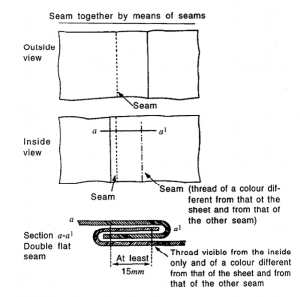
Fig 2 Sheets Made of Several Pieces
one another
(ii) However, where in the case of certain parts of the sheet (such as flaps at the rear and reinforced corners) it is not possible to assemble the pieces in above way, it is to be
sufficient
or 3.2.
to fold the edge of the top section and make the seams as shown in Fig 3.1
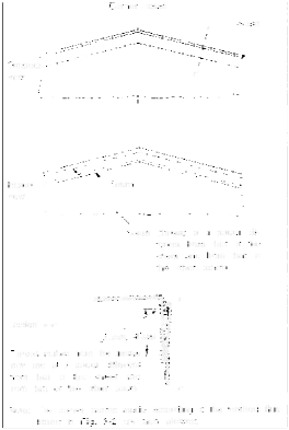
Fig 3.1 Sheets Made of Several Pieces
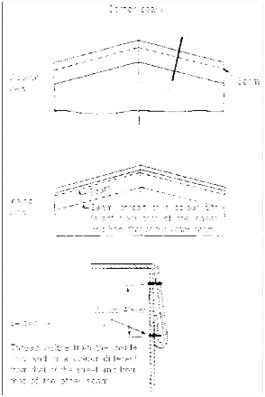
Fig 3.2 Sheets Made of Several Pieces sewn Together
![]()
Ap p e ndi x 3- 1
(iii) One of the seams is to be visible only from the inside and the colour of the thread used for that seam is to be clearly different from the colour of sheet itself and from the colour of the thread used for the other seam.
(iv) All seams are to be machine-sewn.
(d) If the sheet is of plastic-covered cloth, it is to be welded together in the manner of the followings.
(i) If the sheet is made up of several pieces, the pieces may alternatively be welded togeth-
er in the manner shown in Fig 4. The edges of the pieces are to overlap by at least 15 mm . The pieces are to be fused together over the whole width of the overlap.
(ii) The edge of the outer sheet are to be covered with a band of plastic material at least 7
mm wide, affixed by the same welding process as above.
(iii) The plastic band and a width of at least 3 mm on each side are to have a well-marked uniform relief stamped on it. (shown in Fig 4)
(iv) The pieces are to be welded in such a way that they cannot be separated and rejoined
without leaving visible traces.
(e) The sheets may be provided with a flaps, known as tensioning flaps, conforming to the fol- lowing requirements. However, such flaps have been used to conceal horizontal slits made in the sheets giving improper access to the goods carried in the containers. It is therefore recommended that the use of flaps of this type should not be allowed.
(i) A flap sewn or welded on the inside of the sheet in accordance with the requirements
(c) and (d), (A), 5.
(ii) Small individual flaps each pierced by one eyelet secured to the outside surface of the sheet and spaced at such distances as will permit an adequate tensioning of the sheet.
![]()
Ap p e ndi x 3- 1
Fig 4 Sheets Made of Several Pieces
(B) fastening devices of sheet
(a) The following types of fastening are to be provided to the sheeted container for the fixture of the sheet.
(i) metal ring (fixed ring or sliding ring) or swivel ring fixed to the container.
(ii) eyelets to be reinforced enough in the edge of the sheet.
(iii) a fastening passing through the rings above the sheet and visible from the outside for its entire length.
(b) Metal ring or swivel ring of above (i) are to meet the following requirements.
(i) Fixed Ring
① The rings are so affixed to the container that they cannot be removed and replaced
without leaving visible traces.
② The rings are affixed on condition hat spaces between them shall not exceed 200
mm . However, spaces exceeding 200 mm but not exceeding 300 mm are acceptable
over the uprights if the rings are recessed in the side boards and the eyelets are
oval and so small that they can just pass over the rings.
(ii) Sliding Ring
Metal securing rings sliding on metal bars fixed to the containers are to comply with
the following requirements. (see Fig 5)
① The bars are affixed to the container at maximum spacings of 600 mm and in such
a manner that they cannot be removed and replaced without leaving obvious traces.
② Number of sliding rings are as many as the numbers of eyelets that are affixed in
the edge of the sheet at maximum spacings of 200 mm .
③ The sliding rings are made with a double hoop or equipped with a central bar
which is made in one piece without the use of welding. (refer to Fig 5)
(iii) Swivel Ring
Metal swivel rings are to comply with the following requirements. (see Fig 6)
① They rotates in a metal bracket fixed to the container on the condition that it can-
not be removed and replaced without leaving visible traces.
② Each bracket is affixed to the container in such a manner that it cannot be removed
and replaced without leaving visible traces.
③ The spring under each bracket is completely enclosed by a bell-shaped metal cover.
④ Spaces between each swivel-ring are to comply with the requirement in ②, (i), (b),
(B), 5.
Fig 5 Sheeted Containers with Sliding Rings
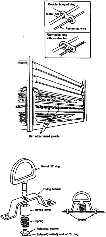
Fig 6 Example of Swivel Ring I'D' Ring
![]()
Ap p e ndi x 3- 1
Ap p e ndi x 3- 1
![]()
(iv) Position of rings to be affixed
The sheet is to overlap solid parts of the container the centre of the securing rings, unless the system itself prevents all access to the goods.
(c) The following fastenings are to be used;
(i) Steel wire ropes of at least 3 mm in diameter; This
by at least 250 mm , measured from of construction of the container by
wire rope to be comprised a textile
(d)
core surrounded by four strands consisting solely of steel wire. Also, wire ropes may have a transparent sheath of unstretchable plastic.
(ii) A rope of hemp or sisal of at least 8 mm in diameter encased in a transparent un-
stretchable plastic sheath.
Each rope used for sheeted container (including the rope of (c) (B), 5) is to be satisfied following requirements.
(i) Each rope is to be in one piece
(ii) Each rope is to have a hard metal end piece at each end.
(iii) The fastener of each metal end-piece is to include a hollow rivet passing through the rope as well as solid rivet.
(iv) A hollow rivet is to allow the passing of the thread or the strap of the Customs seal
(minimum dimensions of the hole: width 3 mm, length 11 mm , or diameter 11 mm ).
(v) The rope is to remain visible on either side of the hollow rivet so that it is possible to ensure that the rope is in one piece (see Fig 7)
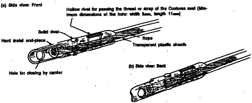
Fig 7 Specimen of End Piece
(e) At the openings in the sheet, used for loading and unloading, the sheet is to meet the fol- lowing requirements.
(i) The two edges of the sheet is to have an adequate overlap. They are to also be fas-
tened by:
① a flap sewn or welded in accordance with the requirements in (c) and (d), (A). A
flap is not to be required if a special device, such as a baffle plate, is fitted, which
prevents access to the goods without leaving visible traces.
② rings and eyelets in accordance with the requirements in (i) and (ii), (a), (B), 5,
and (i), (b), (B), 5.
③ a thong made of appropriate material, in one piece and unstretchable, at least 20
mm wide and 3 mm thick, passing through the rings and holding together the two
edges of the sheet and the flap; the thong is to be secured inside the sheet and fit-
ted with an eyelet to take the rope mentioned in (c) (B).
(ii) The following materials are regarded as suitable for making thongs:
① leather
② non-tensile textile materials including plastic-covered or rubberized cloth, provided
that such materials cannot after severance be welded or reconstituted without leaving
visible traces.
③ Furthermore, the plastic material used to cover thongs is to be transparent and
smooth-surfaced.
Ap p e ndi x 3- 1
![]()
(C) Sheets-fixation to the container
(a) The identification marks, which must appear on the container, and the approval plate is to in no circumstances be covered by the sheet.
(b)
The sheet is to be fixed to the container in strict compliance with the conditions set forth in (1) and (2), Article 2.
(c) Example
Fig 8.
of a system of affixing sheets around containers' corner-castings is given in the
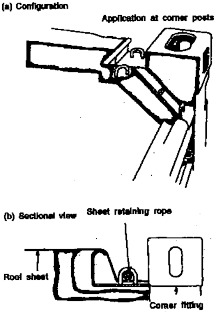
Fig 8 Device for Affixing Sheets Around Containers' Corner Castings
(d) The
containers having permanently - secured sheets are to meet the following requirements.
(see Fig 9.1 and 9.2)
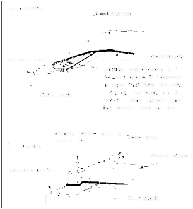
Fig 9.1 Example of a Device for
Container Sheets
Fastening
![]()
Ap p e ndi x 3- 1

Fig 9.2 Example of a Device for Fastening Container Sheets
(i) When the edge of a sheet is to be permanently secured to a container, the joint is to be continuous and effected by means of solid devices.
(ii) Where one or more edges of the sheet are permanently attached to the body of the
container, the sheet is to be held in place by one strip of metal or other suitable mate- rial secured to the body of the container by joining devices complying with the require- ment in (b), (A), 3.
(2) Repairs are to be made in accordance with following ways.
(a) The edges are to be folded into one another and sewn together with two visible seams at least 15 mm apart.
(b) The colour of the thread visible from the inside is to be different from that of the thread visi- ble from the outside and from that of the sheet itself; (see Fig 10)
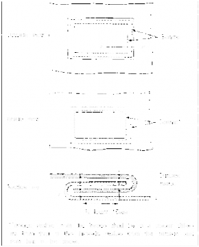
Fig 10 Repair of the Sheets
Ap p e ndi x 3- 1
![]()
(c) All seams are to be machine-sewn.
(d) When a sheet which has been damaged near the edges is repaired by replacing the damaged part by a patch, the seam can also be made in accordance with the requirements in (c), (A), (1).
(e) Sheets of plastic-covered cloth may alternatively be repaired in accordance with the method de- scribed in (d), (A), (1), but in that case the weld must be made on both sides of the sheet, the patch being fitted on the inside of the sheet. ![]()
![]()